| Sign In | Join Free | My infospaceinc.com |
|
| Sign In | Join Free | My infospaceinc.com |
|
| Categories | Taconic PCB |
|---|---|
| Solder mask: | No |
| PCB Thickness: | 0.85mm |
| PCB size: | 76.4mm × 98.6mm with ±0.15mm dimensional tolerance |
| Layer count: | Single Sided |
| Copper weight: | 1oz (1.4 mils) outer layers |
| Silkscreen: | White |
| Surface finish: | Pure Gold |
| Brand Name: | Bicheng |
| Certification: | UL, ISO9001, IATF16949 |
| Place of Origin: | CHINA |
| MOQ: | 1PCS |
| Price: | USD9.99-99.99/PCS |
| Payment Terms: | T/T |
| Supply Ability: | 5000PCS per month |
| Delivery Time: | 8-9 working days |
| Packaging Details: | Vacuum bags+Cartons |
| Material: | Taconic TLX-8 |
| Company Info. |
| Bicheng Electronics Technology Co., Ltd |
| Verified Supplier |
| View Contact Details |
| Product List |
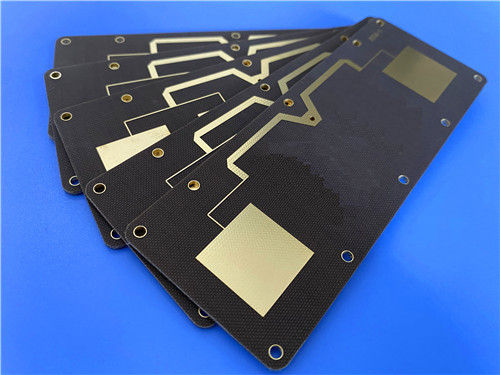
The 2-layer Taconic TLX-8 rigid RF PCB is a high-reliability circuit board built with PTFE fiberglass laminate, specifically engineered for high-volume antenna systems and general microwave RF applications. Utilizing Taconic TLX-8 core substrate and standard 1oz outer copper layers, this 0.85mm thin high-frequency PCB adopts premium Pure Gold surface finishing and meets full IPC-Class-2 quality compliance. Each PCB undergoes 100% electrical testing prior to delivery, delivering ultra-low dielectric loss, tightly controlled dielectric constant, outstanding PIM performance, and exceptional resistance to harsh environments.
What Is Taconic TLX-8? Advanced Substrate Introduction
Taconic TLX-8 is a premium-grade PTFE fiberglass laminate widely adopted as a high-volume antenna substrate for a broad range of RF and microwave applications. Featuring flexible customizable thickness options and various copper cladding choices, this high-frequency material is highly optimized for low-layer-count microwave PCB layouts. It provides superior mechanical reinforcement and robust environmental endurance, making it an ideal substrate solution for electronic assemblies operating in extreme working conditions.
Taconic TLX-8 substrate delivers outstanding anti-creep performance under high-vibration operating conditions, reliable heat resistance for engine-mounted modules, radiation tolerance for space-grade devices, extreme seawater resistance for naval ship antennas, and consistent thermal stability for flight altimeter substrates. Thanks to its versatile environmental adaptability, Taconic TLX-8 PCBs maintain stable RF circuit performance across aerospace, marine, automotive, and industrial microwave systems.

Core Benefits of Taconic TLX-8 PCB
Taconic TLX-8 high-frequency PCB material combines superior electrical characteristics, stable mechanical properties, and reliable safety ratings, delivering comprehensive technical advantages:
Superior PIM Performance: Achieves passive intermodulation performance below -160 dBc, ensuring ultra-clean signal quality for sensitive antenna and communication systems
Consistent Electrical Properties: Features low, tightly controlled dielectric constant (Dk) and ultra-low dissipation factor (Df), minimizing high-frequency signal attenuation and maintaining stable transmission efficiency.
Enhanced Mechanical & Thermal Stability: Offers excellent dimensional stability and balanced thermal expansion behavior to prevent structural deformation during thermal cycling and mechanical stress
Minimal Moisture Absorption: Extremely low water absorption rate prevents electrical parameter deviation in high-humidity environments
High Flame Retardancy: Complies with UL 94 V0 safety standards, ensuring secure operation of high-frequency electronic equipment in industrial environments
Optimized Cost-Performance: Specially engineered for low-layer microwave PCB designs, balancing premium RF performance with cost-effective mass manufacturability
Properties of Taconic TLX-8
| TLX-8 TYPICAL VALUES | |||||
| Property | Test Method | Unit | Value | Unit | Value |
| DK @10 GHz | IPC-650 2.5.5.3 | 2.55 | 2.55 | ||
| Df @1.9 GHz | IPC-650 2.5.5.5.1 | 0.0012 | 0.0012 | ||
| Df @10 GHz | IPC-650 2.5.5.5.1 | 0.0017 | 0.0017 | ||
| Dielectric Breakdown | IPC-650 2.5.6 | kV | >45 | kV | >45 |
| Moisture Absorption | IPC-650 2.6.2.1 | % | 0.02 | % | 0.02 |
| Flexural Strength(MD) | ASTM D 709 | psi | 28,900 | N/mm2 | |
| Flexural Strength(CD) | ASTM D 709 | psi | 20,600 | N/mm2 | |
| Tensile Strength(MD) | ASTM D 902 | psi | 35,600 | N/mm2 | |
| Tensile Strength(CD) | ASTM D 902 | psi | 27,500 | N/mm2 | |
| Elongation at Break(MD) | ASTM D 902 | % | 3.94 | % | 3.94 |
| Elongation at Break(CD) | ASTM D 902 | % | 3.92 | % | 3.92 |
| Young's Modulus(MD) | ASTM D 902 | kpsi | 980 | N/mm2 | |
| Young's Modulus(CD) | ASTM D 902 | kpsi | 1,200 | N/mm2 | |
| Young's Modulus(MD) | ASTM D 3039 | kpsi | 1,630 | N/mm2 | |
| Poisson's Ratio | ASTM D 3039 | 0.135 | N/mm | ||
| Peel Stength(1 oz.ed) | IPC-650 2.4.8 Sec.5.2.2(Thermal Stress.) | Ibs./linear inch | 15 | N/mm | |
| Peel Stength(1 oz.RTF) | IPC-650 2.4.8 Sec.5.2.2(Thermal Stress.) | Ibs./linear inch | 17 | N/mm | |
| Peel Stength(½ oz.ed) | IPC-650 2.4.8.3(Elevated Temp.) | Ibs./linear inch | 14 | N/mm | |
| Peel Stength(½ oz.ed) | IPC-650 2.4.8 Sec.5.2.2(Thermal Stress.) | Ibs./linear inch | 11 | N/mm | |
| Peel Stength(1 oz.rolled) | IPC-650 2.4.8 Sec.5.2.2(Thermal Stress.) | Ibs./linear inch | 13 | N/mm | 2.1 |
| Thermal Conductivity | ASTM F433/ASTM 1530-06 | W/M*K | 0.19 | W/M*K | 0.19 |
| Dimensional Stability(MD) | IPC-650 2.4.39 Sec.5.5(After Bake.) | mils/in. | 0.06 | mm/M | |
| Dimensional Stability(CD) | IPC-650 2.4.39 Sec.5.4(After Bake.) | mils/in. | 0.08 | mm/M | |
| Dimensional Stability(MD) | IPC-650 2.4.39 Sec.5.5(Thermal Stress.) | mils/in. | 0.09 | mm/M | |
| Dimensional Stability(CD) | IPC-650 2.4.39 Sec.5.5(Thermal Stress.) | mils/in. | 0.1 | mm/M | |
| Surface Resistivity | IPC-650 2.5.17.1 Sec.5.2.1(Elevated Temp.) | Mohm | 6.605 x 10⁸ | Mohm | 6.605 x 10⁸ |
| Surface Resistivity | IPC-650 2.5.17.1 Sec.5.2.1(Humidity Cond.) | Mohm | 3.550 x 10⁶ | Mohm | 3.550 x 10⁶ |
| Volume Resistivity | IPC-650 2.5.17.1 Sec.5.2.1(Elevated Temp.) | Mohm/cm | 1.110 x 10¹⁰ | Mohm/cm | 1.110 x 10¹⁰ |
| Volume Resistivity | IPC-650 2.5.17.1 Sec.5.2.1(Humidity Cond.) | Mohm/cm | 1.046 x 10¹⁰ | Mohm/cm | 1.046 x 10¹⁰ |
| CTE(X axis)(25-260℃) | IPC-650 2.4.41/ASTM D 3386 | ppm/℃ | 21 | ppm/℃ | 21 |
| CTE(Y axis)(25-260℃) | IPC-650 2.4.41/ASTM D 3386 | ppm/℃ | 23 | ppm/℃ | 23 |
| CTE(Z axis)(25-260℃) | IPC-650 2.4.41/ASTM D 3386 | ppm/℃ | 215 | ppm/℃ | 215 |
| Density(Specific Gravity) | ASTM D 792 | g/cm3 | 2.25 | g/cm3 | 2.25 |
| Td(2% Weight Loss) | IPC-650 2.4.24.6(TGA) | ℃ | 535 | ℃ | |
| Td(5% Weight Loss) | IPC-650 2.4.24.6(TGA) | ℃ | 553 | ℃ | |
| Flammability Rating | UL-94 | V-0 | V-0 | ||
Key PCB Construction Specifications
| Parameter Item | Specific Specification |
| Base Material | Taconic TLX-8 PTFE fiberglass high-frequency laminate |
| Layer Count | 2 layers (double-sided rigid PCB structure) |
| Board Dimensions | 76.4mm × 98.6mm with ±0.15mm dimensional tolerance (1 piece) |
| Minimum Trace/Space | 5/7 mils minimum trace and space |
| Minimum Hole Size | 0.3mm minimum hole size |
| Via Design | Through-hole-only structure with no blind vias |
| Finished Board Thickness | 0.85mm |
| Finished Copper Weight | 1oz (1.4 mils) outer copper weight |
| Via Plating Thickness | 20μm via plating thickness, providing durable via conductivity and long-term soldering reliability |
| Surface Finish | Pure Gold surface finish, delivering superior corrosion resistance, excellent solderability, and stable high-frequency performance |
| Silkscreen | White top silkscreen with no bottom silkscreen for clear component labeling and easy assembly identification |
| Solder Mask | No top and bottom solder mask, maximizing heat dissipation and preserving original high-frequency electrical performance |
| Quality Test Standard | 100% electrical testing before shipment |
2-Layer Taconic TLX-8 PCB Stack-up Structure
This 2-layer rigid PCB stack-up features genuine Taconic TLX-8 PTFE fiberglass core substrate paired with high-purity copper layers. This standardized low-loss stack-up provides tightly controlled dielectric parameters, excellent mechanical sturdiness, and outstanding environmental tolerance, perfectly matching low-layer-count microwave and high-frequency RF design requirements.
| Layer Sequence | Material Specification | Thickness | Core Function |
| Outer Layer 1 (Top) | Conductive copper foil | 35μm | Primary signal transmission and SMT soldering layer for high-frequency RF circuits |
| Core Dielectric Layer | Taconic TLX-8 PTFE fiberglass laminate | 0.762mm (30mil) | Low-loss dielectric isolation layer with stable Dk/Df characteristics and extreme environmental resistance for microwave applications |
| Outer Layer 2 (Bottom) | Conductive copper foil | 35μm | Secondary conductive layer to balance structural stability and overall circuit performance |
PCB Statistics
| Parameter Item | Specific Value |
| Components | 30 |
| Total Pads | 41 |
| Thru Hole Pads | 25 |
| Top SMT Pads | 16 |
| Bottom SMT Pads | 0 |
| Vias | 27 |
| Nets | 2 |
Accepted Artwork Format: We support standard Gerber RS-274-X files for custom PCB manufacturing, enabling precise fabrication and efficient technical collaboration with global customers.
Quality Standard: All PCBs are manufactured and inspected in accordance with IPC-Class-2 industrial standards, ensuring consistent batch quality and long-term operational reliability.
Global Service: We provide worldwide custom PCB quotation, professional technical consultation, and global shipping services for all customization projects.
Typical Application Scenarios
Radar Systems: High-stability substrate solutions for industrial detection and aerospace radar signal processing hardware
Mobile Communications: High-reliability circuit boards for cellular base stations and mobile signal transmission devices
Microwave Test Equipment: Precision PCB substrates for laboratory microwave testing, measurement, and calibration instruments
Microwave Transmission Devices: Low-loss circuit boards dedicated to microwave signal transmission and communication link systems
RF Passive & Active Components: Custom PCBs for RF couplers, splitters, combiners, power amplifiers, and high-frequency antenna assemblies
In conclusion, this 2-layer Taconic TLX-8 rigid PCB utilizes high-performance PTFE fiberglass substrate to deliver ultra-low Df loss, tightly controlled Df values, excellent PIM stability, and strong environmental adaptability. As a cost-effective and highly reliable solution for low-layer microwave designs, this high-frequency PCB is extensively applied in radar systems, mobile communication infrastructure, and precision microwave test equipment.


|
 TLF-35 400x500mm Multilayer Taconic PCB Board Bare Copper Surface Finish
Taconic TLX RF PCB Board
RF-35TC 0.3mm Copper 1oz RF Taconic PCB High Frequency Circuit Board
Double Sided Taconic PCB 10mil RF-35TC 0.254mm Ceramic PCB Board For Filters And Couplers
RF-35 30mil Double Sided Taconic PCB Immersion Gold Printed Circuit Board
RF-60TC PTFE Based 60mil Coating RF Circuit Board Hasl Surface Finish
RF-35TC 20mil 0.508mm Taconic PCB Two Layer PCB ENIG Surface Finish
6.0mm F4B High Frequency Taconic PCB DK 4.4 PTFE Microwave PCB
Double Layer RF-35A2 PCB 20mil Taconic PCB With Immersion Gold
Taconic 31mil TLX-8 PCB 2-layer Immersion Gold
TLF-35 400x500mm Multilayer Taconic PCB Board Bare Copper Surface Finish
Taconic TLX RF PCB Board
RF-35TC 0.3mm Copper 1oz RF Taconic PCB High Frequency Circuit Board
Double Sided Taconic PCB 10mil RF-35TC 0.254mm Ceramic PCB Board For Filters And Couplers
RF-35 30mil Double Sided Taconic PCB Immersion Gold Printed Circuit Board
RF-60TC PTFE Based 60mil Coating RF Circuit Board Hasl Surface Finish
RF-35TC 20mil 0.508mm Taconic PCB Two Layer PCB ENIG Surface Finish
6.0mm F4B High Frequency Taconic PCB DK 4.4 PTFE Microwave PCB
Double Layer RF-35A2 PCB 20mil Taconic PCB With Immersion Gold
Taconic 31mil TLX-8 PCB 2-layer Immersion Gold

