| Sign In | Join Free | My infospaceinc.com |
|
| Sign In | Join Free | My infospaceinc.com |
|
| Categories | ABB PLC |
|---|---|
| Brand Name: | ABB |
| Model Number: | NTAC-02 |
| Place of Origin: | SWEDEN |
| MOQ: | 1 |
| Price: | 66USD |
| Payment Terms: | T/T |
| Supply Ability: | in stock |
| Delivery Time: | 2-3 work days |
| Packaging Details: | Brand new and original |
| Brand: | ABB |
| Description: | Pulse Encoder Interface |
| Part number: | NTAC-02 |
| Place of shipment: | Xiamen, China |
| Country of origin: | SWEDEN |
| Packaging: | Original New Packaging |
| MOQ: | 1 Piece |
| Shipping: | TNT, DHL, FedEx, EMS, UPS |
| Company Info. |
| AMIKON LIMITED |
| Verified Supplier |
| View Contact Details |
| Product List |

| Category | Item | Specification |
|---|---|---|
| Enclosure | Housing | Plastic shell |
| Dimensions | 45 mm * 75 mm * 105 mm | |
| Protection class | IP20 | |
| Installation | Mounting method | Mounted on standard DIN rail |
| Hardware Settings | DIP switches | 7 DIP switches for node address setting |
| Default pre-assigned address | 16 | |
| Type | Specification |
|---|---|
| Optical TX/RX | Hewlett-Packard universal connector for ACS600 connection |
| Terminal blocks | Phoenix Contact MVBSTW 2,5/8-ST-5,08 |
| Wire cross-section | 0.5 to 2.5 mm² |
| Parameter | Specification |
|---|---|
| Max. signal frequency | 100 kHz |
| Logic level thresholds (15 V supply) | "1" > 7.6 V, "0" < 5 V |
| Logic level thresholds (24 V supply) | "1" > 12.2 V, "0" < 8 V |
| Speed feedback resolution | 0.00305% (15-bit) |
| Isolation | Inputs isolated from power supply and ground |
| Channel A/B phase shift | 90° electrical |
| Channel Z | 1 pulse per revolution (for positioning) |
| Parameter | Specification |
|---|---|
| Power consumption | Max. 250 mA at 24 V DC (typical) |
| Material approvals | All materials UL/CSA approved |
| Fast transient immunity (IEC 801-4) | 4 kV, 5/50 ns |
| Electromagnetic emission | Complies with EN 55022 Class B |

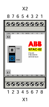
| Terminal | Marking | Description |
|---|---|---|
| 1 | -V | Encoder power supply, 15 or 24 V d.c. (depends on jumper settings at terminals 4, 5, 6). Max 5 W. (For single-ended grounded encoder connections: still use -V to balance A+, B+, Z+ signals). |
| 2 | -V | |
| 3 | +V | |
| 4 | 24/15 | Encoder Supply Voltage Selection. Terminals 4 and 5 connected: Encoder supply voltage is 15 V. Terminals 4 and 6 connected: Encoder supply voltage is 24 V. (NTAC module provides 2 jumpers). |
| 5 | 15 | |
| 6 | 24 | |
| 7 | 0V | NTAC module power supply, 24 V d.c. +/-10% (See next section for current consumption). |
| 8 | +24V |
| Terminal | Marking | Description |
|---|---|---|
| 1 | A+ | A |
| 2 | A- | A‾ |
| 3 | B+ | B |
| 4 | B- | B‾ |
| 5 | Z+ | Z |
| 6 | Z- | Z‾ |
| 7 | SH | Shield - Used for encoder cable grounding. Internally connected to NTAC module ground. |
| 8 | SH | Shield |


| Module | Application Program | Circuit Board | Channel | Terminal |
|---|---|---|---|---|
| NTAC-02 | Standard, V5.0 and later | NDCO (Optional) | CH2 | V17, V18 |
| Standard, V5.0 and later; Master/Follower Application Macro | NAMC | CH1 | V15, V16 | |
| System | NAMC | CH1 | V15, V16 | |
| Crane, V5.0 and later | NAMC | CH1 | V15, V16 | |
| NDIO-02,NAIO-03 (All) | NAMC | CH1 | V15, V16 |
The module connects to the drive (NAMC/NDCO board) via fiber optic cables. Please note the color coding of the fiber optic connectors:
The terminals connected to NTAC-02, NDIO-02, and NAIO-03 modules are shown in the table above.

At Amikon, you will be working directly with one dedicated Account Manager for every enquiry you submit. Your Account Manager is fully trained and understands that you are always looking for:
They will remain completely open, honest, and available to assist you with even the smallest questions at any time.
Timescales are crucial in our industry. Your Account Manager will always provide accurate lead times for every enquiry. Amikon prides itself on delivering goods exactly when promised, and we can work with any carrier you request, keeping you updated with tracking numbers throughout the entire process.
Amikon not only maintains a vast selection of in-stock items, but also works closely with manufacturers and suppliers worldwide to secure the best price for every enquiry.

|
 ABB 07KP90 Communications Module with 24V DC Supply Voltage Compatible with Advant Controller 31
ABB Bailey IEPAS02 AC System Power Module
ABB Bailey NTAO02 Termination Unit
ABB Bailey NTMP01 Multi-Function Processor Termination Unit
ABB DSAI130D 3BSE003127R1 16-bit Resolution Analog Input Board with ±0.05% Accuracy
ABB Bailey NTDI02 Digital I/O Termination Unit
ABB SPBRC400 BRC400 P-HC-BRC-40000000 Harmony Rack Bridge Controller with 2 MB NVRAM
ABB INNPM12 Network Processing Module for Harmony Rack Cnet
ABB Bailey NTCL01 Communication Termination Unit
ABB PM891K01 Processor Unit
ABB 07KP90 Communications Module with 24V DC Supply Voltage Compatible with Advant Controller 31
ABB Bailey IEPAS02 AC System Power Module
ABB Bailey NTAO02 Termination Unit
ABB Bailey NTMP01 Multi-Function Processor Termination Unit
ABB DSAI130D 3BSE003127R1 16-bit Resolution Analog Input Board with ±0.05% Accuracy
ABB Bailey NTDI02 Digital I/O Termination Unit
ABB SPBRC400 BRC400 P-HC-BRC-40000000 Harmony Rack Bridge Controller with 2 MB NVRAM
ABB INNPM12 Network Processing Module for Harmony Rack Cnet
ABB Bailey NTCL01 Communication Termination Unit
ABB PM891K01 Processor Unit

