Sign In | Join Free | My infospaceinc.com
infospaceinc.com
Products
Search by Category
Home > Toy Parts >

Compact Efficient PQ50 High Frequency LLC Transformer Low Loss Stable For UPS

Categories High Frequency LLC
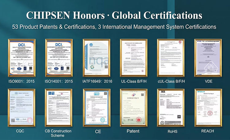
Certification: UL/cUL Class B/F/H, VDE, CQC
Topology: LLC Resonant Converter
Model Number: PQ50
Switching device: MOSFET or GaN transistors
MOQ: 1K
Delivery Time: 7-14 work days (Negotiable)
Operating frequency: above 100 kHz
Payment Terms: T/T
Price: $1.35-2.68/pieces
Power range: 300 W to 3 kW
Supply Ability: 10000pcs
Brand Name: CHIPSEN
Efficiency: >90%
Place of Origin: China
Input voltage range: 85-265 VAC
  • Haven't found right suppliers
  • Our buyer assistants can help you find the most suitable, 100% reliable suppliers from China.
  • And this service is free of charge.
  • we have buyer assistants who speak English, French, Spanish......and we are ready to help you anytime!
Submit Buying Request
  • Product Details
  • Company Profile

Compact Efficient PQ50 High Frequency LLC Transformer Low Loss Stable For UPS

Compact Efficient PQ50 High Frequency Transformer Low Loss Stable for UPS
The PQ50 is a high frequency ferrite transformer platform developed for compact isolated power conversion. Its PQ core geometry provides a relatively large magnetic cross section and winding area within a compact installation envelope, making it suitable for applications requiring power density, efficiency, controlled leakage inductance, and stable thermal performance.
The image shows two magnetic assemblies installed on a shared base. This may represent a customer-specific transformer assembly rather than one standard PQ50 configuration. The quantity of magnetic components, wiring arrangement, mounting base, and electrical relationship must be confirmed through the approved drawing.
All numerical values below are typical engineering inquiry references rather than guaranteed ratings. Final performance depends on converter topology, input voltage, output requirements, switching frequency, duty cycle, waveform, cooling method, insulation system, and allowable temperature rise.
Industry Applications & Specifications
Industry and ApplicationTypical Operating ConditionsParameters Prioritized by BuyersTypical Inquiry ReferenceChippsen Customization Support
UPS EquipmentBattery supplied full bridge, push pull, half bridge or LLC conversionTurns ratio, power rating, inductance, leakage, efficiency and overload capabilityApproximately 20 kHz to 200 kHz depending on topologyTurns ratio, windings, inductance, terminals, mounting and thermal design
Industrial Power SuppliesIsolated AC/DC and DC/DC switching stagesPower density, DCR, temperature rise, regulation, insulation and dimensionsApproximately 300 W to 3 kW depending on construction and coolingCore material, conductor type, pinout, shielding and mounting
Energy Storage SystemsBattery converter, PCS and auxiliary power supplyBidirectional current, RMS current, peak current, efficiency and insulationProject specific battery voltage and converter powerCustom turns ratio, conductors, inductance, mechanical assembly and protection
Solar InvertersIsolated DC/DC stage and auxiliary switching supplyHigh voltage isolation, core loss, leakage inductance and operating lifeDC bus and switching conditions defined by the inverter designReinforced insulation, shielding, low loss winding and thermal optimization
Industrial Battery ChargersIsolated charging converterCharging voltage, current, efficiency, insulation and temperature riseApplication specific battery voltage and charging profileMultiple outputs, high current conductors, terminals and thermal sensing
EV Charging EquipmentAuxiliary power or isolated DC/DC conversionIsolation, interwinding capacitance, efficiency, thermal cycling and power densityLLC and phase shifted full bridge converters commonly requestedLow capacitance winding, reinforced insulation and custom pinout
Telecom Power SystemsRectifier and isolated 48 V DC conversionCompact size, efficiency, DCR, EMI and continuous reliabilityHigh frequency bridge or resonant conversionLow loss conductor, shielding and footprint customization
Server Power SuppliesHigh density isolated converterEfficiency, leakage inductance, capacitance, thermal performance and heightFrequency and power defined by server power architectureLow profile winding, pinout, conductors and cooling optimization
Industrial Welding EquipmentHigh current switching conversionPeak current, copper loss, leakage inductance and mechanical strengthPulsed or continuous load according to welding cycleParallel wire, litz wire, foil and heavy terminal construction
Medical Power EquipmentIsolated high frequency supplyLeakage current, dielectric strength, capacitance and temperature riseParameters defined by equipment safety classificationReinforced insulation, shielding, testing and documentation
Motor DrivesIsolated auxiliary supply or main DC/DC stageMultiple outputs, isolation, regulation, EMI and reliabilityInput and output conditions defined by drive architectureMultiple isolated windings, shields and custom connection layout
Automation EquipmentController power and isolated industrial converterCompact footprint, stable output, efficiency and PCB compatibilityApplication specific voltage, power and frequencyPinout, dimensions, output windings, marking and mounting
Customization Parameters
ParameterTypical Inquiry ReferenceCustomization Status
Core PlatformPQ50 ferrite core assemblyCustomizable
Magnetic MaterialMnZn power ferrite selected according to frequency, loss and temperatureCustomizable
Converter TopologyFlyback, forward, push pull, half bridge, full bridge, LLC or phase shifted full bridgeCustomer Specified
Switching FrequencyApproximately 20 kHz to 300 kHz commonly evaluatedCustomer Specified
Power RangeApproximately 300 W to 3 kW depending on topology, cooling and temperature riseTo Be Confirmed
Input VoltageMinimum, nominal and maximum converter input voltageCustomer Specified
Output VoltageNo load, nominal and full load output voltageCustomer Specified
Turns RatioDeveloped according to voltage waveform, duty cycle and rectification methodCustomizable
Primary InductanceDefined at the agreed frequency, voltage and test connectionCustomer Specified
Leakage InductanceMinimized or intentionally controlled according to converter requirementsCustomizable
RMS CurrentContinuous RMS current required for each windingCustomer Specified
Peak CurrentMaximum repetitive and transient winding currentCustomer Specified
DC ResistanceMaximum DCR for each winding at the specified temperatureCustomizable
Winding ConductorRound wire, parallel wire, litz wire, copper foil or combined constructionCustomizable
Interwinding CapacitanceControlled according to EMI and common mode current requirementsCustomizable
Insulation SystemBasic, supplementary, reinforced or project specific insulationCustomizable
Dielectric StrengthCommon inquiries may require approximately 1.5 kV AC to 5 kV ACCustomer Specified
Creepage and ClearanceDefined by working voltage, applicable standard and insulation materialCustomer Specified
Insulation ClassClass B, Class F, Class H or project specific systemCustomizable
Temperature RiseDefined according to load, ambient temperature, cooling and enclosureCustomer Specified
Cooling MethodNatural air, forced air, conduction or customer system coolingCustomer Specified
Electrostatic ShieldSingle or multiple shielding layersOptional
Thermal ProtectionThermal fuse, thermostat or temperature sensorOptional
Pin ConfigurationPCB pin quantity, spacing, dimensions and electrical assignmentCustomizable
Lead ConnectionsLead wires, connectors, terminals or busbar interfacesCustomizable
MountingPCB mounting, base plate, bracket or customer specified assemblyCustomizable
ImpregnationVarnish impregnation, partial encapsulation or full encapsulationCustomizable
Multiple Component AssemblyTwo or more magnetic components installed on a shared baseOptional
CertificationApplicability evaluated for the exact construction and part numberProject Dependent
MarkingLogo, part number, electrical data, batch and traceability codeCustomizable
PackagingTray, carton or customer specified protective packagingCustomizable
Engineering Information Required for Custom Design
Required InformationEngineering Purpose
Converter TopologyDetermines magnetic operation, winding structure and voltage waveform
Minimum and Maximum Input VoltageEstablishes primary turns and operating flux range
Output Voltage and CurrentDetermines turns ratio, conductor size and output configuration
Continuous and Peak PowerDetermines core utilization, winding capacity and thermal requirements
Switching FrequencySupports core material and conductor selection
Duty CycleRequired for volt-second and flux density calculations
Primary Current WaveformSupports RMS loss, saturation and peak current evaluation
Secondary Current WaveformSupports conductor sizing and thermal calculations
Target Primary InductanceControls magnetizing current and converter behavior
Leakage Inductance LimitInfluences resonance, switching stress and power transfer
Maximum DCRDefines winding conduction loss targets
Interwinding Capacitance LimitSupports common mode EMI control
Isolation RequirementDetermines insulation barriers, materials, creepage and clearance
Maximum DimensionsDefines the available footprint, height and winding envelope
Pinout or Wiring DrawingEnsures compatibility with the customer PCB or harness
Cooling ConditionsRequired for realistic power and temperature evaluation
Ambient TemperatureSupports insulation class and thermal margin selection
Applicable StandardsDefines safety, construction, testing and documentation
Annual DemandSupports material, tooling and production planning
Product Description
The PQ50 high frequency transformer is designed for compact, medium to high power conversion in UPS systems, industrial power supplies, inverters, battery chargers, telecommunications equipment, and renewable energy applications.
Its PQ ferrite core geometry provides efficient utilization of the magnetic cross section and winding window. The structure can accommodate multiple primary and secondary windings, insulation barriers, electrostatic shields, and higher current conductors while maintaining a relatively compact footprint.
Depending on the application, the transformer can use round wire, parallel wire, litz wire, copper foil, or a combined winding structure. Winding sequence can be optimized for leakage inductance, interwinding capacitance, copper loss, insulation, and temperature rise.
The pictured product contains two magnetic assemblies on a common mounting base. Chipsen can provide a single transformer or a customized integrated magnetic assembly according to the customer circuit, mechanical drawing, and wiring requirements.
Product Construction
Construction ElementDescription
Magnetic CorePQ50 MnZn ferrite core selected according to frequency, flux density and loss
BobbinHigh temperature insulating coil former supporting windings and terminals
Primary WindingCopper wire, foil, litz wire or parallel conductor construction
Secondary WindingsSingle or multiple outputs designed according to voltage and current
Insulation BarriersTape margins, sleeving, spacers and reinforced barriers where required
Electrostatic ShieldOptional copper or foil shield for common mode noise control
PCB PinsSolder terminals configured according to the customer PCB
Lead WiresOptional flexible leads, connectors or heavy current terminals
Core RetentionTape, adhesive, clamp or customized mechanical fixation
Mounting BaseOptional shared base for multiple magnetic components
ImpregnationVarnish or encapsulation for winding stability and environmental protection
Thermal DeviceOptional thermal fuse, thermostat or temperature sensor
IdentificationCustomized polarity marking, part number, batch and traceability code
Product Characteristics
  • Compact PQ50 ferrite core geometry
  • High power density design potential
  • Suitable for high frequency switching conversion
  • Low core loss magnetic material options
  • Low copper resistance winding configurations
  • Custom primary and secondary voltage ratios
  • Controlled magnetizing and leakage inductance
  • High current conductor options
  • Single or multiple secondary outputs
  • Reinforced insulation options
  • Low interwinding capacitance design available
  • Optional electrostatic shielding
  • Custom PCB pinout and mounting structure
  • Optional multi-transformer integrated assembly
  • Optional thermal sensing and protection
  • Drawing-based and sample-based replacement development
Applications
  • Uninterruptible power supplies
  • Industrial switching power supplies
  • Industrial power inverters
  • Solar inverters
  • Energy storage converters
  • Battery PCS equipment
  • Industrial battery chargers
  • EV charging equipment
  • High power DC/DC converters
  • Telecom rectifiers
  • Server power supplies
  • Industrial welding equipment
  • Motor drive power supplies
  • Automation equipment
  • Medical power supplies
  • Full bridge converters
  • Phase shifted full bridge converters
  • LLC resonant converters
Quality Control
Chipsen establishes the manufacturing and inspection plan according to the approved electrical specification, mechanical drawing, converter conditions, and customer quality requirements.
Incoming ferrite cores, copper conductors, bobbins, insulation materials, pins, lead wires, adhesives, and protection devices are inspected before production. Winding, insulation, assembly, impregnation, termination, testing, marking, and packaging are controlled through documented procedures.
Inspection ItemInspection Purpose
Turns Ratio TestConfirms the required primary and secondary voltage relationship
Primary Inductance TestVerifies magnetizing inductance at the specified test condition
Leakage Inductance TestConfirms coupling and converter compatibility
Winding Resistance TestEvaluates conductor consistency and copper loss
Polarity and Phase TestConfirms winding orientation and multiple output relationships
Insulation Resistance TestEvaluates insulation between windings, core, pins and leads
Dielectric Strength TestVerifies the specified isolation withstand capability
Interwinding Capacitance TestAvailable for EMI sensitive applications
Temperature Rise TestConfirms thermal performance under agreed operating conditions
Load Performance TestEvaluates voltage, current, loss and efficiency
Core Loss EvaluationConfirms magnetic performance under the defined waveform
Pin Strength TestEvaluates the mechanical reliability of PCB terminals
Solderability TestConfirms compatibility with the agreed soldering process
Lead Pull TestEvaluates the mechanical strength of lead connections
Dimension InspectionVerifies footprint, height and mounting dimensions
Impregnation InspectionChecks material coverage, cleanliness and assembly
Thermal Device TestConfirms sensor or protector operation where installed
Appearance InspectionChecks polarity marks, insulation, pins, leads and workmanship
Packaging InspectionConfirms protection, quantity, orientation and labels
Special medical, automotive, railway, charging and energy storage applications require separate validation plans. Test conditions, limits and sampling requirements must be defined in the approved specification or quality agreement.
Company Profile
Chipsen specializes in the development and manufacturing of custom magnetic components for industrial equipment, power electronics, automation systems, and electrical control applications.
The product range includes high-frequency transformers, low-frequency transformers, planar transformers, power inductors, high-current inductors, toroidal inductors, common-mode chokes, EMI filter magnetics, wireless charging coils, custom coils, and non-standard magnetic components.
Chipsen supports drawing-based development, sample-based replacement development, and application-requirement design. Engineering discussions can cover low DCR, leakage inductance, EMI, insulation, temperature rise, winding structure, footprint, pinout, terminals, protection devices, and production-testing requirements.
The objective is to provide evaluation-ready samples and a clearly defined specification before production approval.
Why Choose Chipsen
  • PQ50 high frequency transformer customization
  • Compact high power density magnetic design
  • Engineering evaluation based on actual converter conditions
  • Drawing based and sample based replacement development
  • Custom turns ratio, inductance, leakage and DCR
  • Round wire, litz wire, copper foil and parallel winding options
  • Reinforced insulation and controlled creepage design
  • Low capacitance and electrostatic shielding options
  • Customized PCB pinout, leads and mounting base
  • Single transformer and multiple component assembly options
  • Temperature rise and magnetic loss optimization
  • Optional thermal sensing and protection
  • OEM and ODM customization
  • MOQ from one piece for eligible sample projects
  • Quotation target within three working days after complete requirements are received
  • Sample production target within seven days for eligible designs after technical confirmation
  • Five year warranty with extended warranty evaluation for special industries
  • Extended warranty is subject to application validation and written agreement
  • Electrical and mechanical testing based on approved specifications
  • Clear drawing and specification approval before mass production
Frequently Asked Questions
What information is required to customize a PQ50 transformer?
Please provide the converter topology, input voltage range, output voltage and current, continuous and peak power, switching frequency, duty cycle, current waveform, target inductance, leakage limit, insulation requirement, dimensions, cooling conditions, pinout, and annual demand.
What power can a PQ50 transformer handle?
Approximately 300 W to 3 kW is a broad inquiry reference rather than a guaranteed rating. Actual capacity depends on topology, switching frequency, flux density, winding design, cooling, ambient temperature, efficiency target, and allowable temperature rise.
What is the advantage of a PQ core?
A PQ core provides a relatively large magnetic cross section and winding window within a compact geometry. This can support high power density, efficient winding arrangements, and reduced overall converter size.
Can the PQ50 be used in an LLC converter?
Yes. A PQ50 transformer can be developed for LLC resonant conversion. The resonant frequency range, turns ratio, magnetizing inductance, leakage inductance, gain requirement, and load range must be provided.
Can leakage inductance be customized?
Yes. Leakage inductance can be minimized for efficient coupling or intentionally controlled for resonant operation. The required value, tolerance, frequency, and test connection must be specified.
Can the transformer use litz wire or copper foil?
Yes. Round wire, parallel wire, litz wire, copper foil, and combined winding structures can be evaluated according to frequency, current, loss, winding space, and termination requirements.
Can multiple secondary outputs be provided?
Yes. Multiple isolated or connected secondary windings can be developed when winding space, power distribution, insulation, and thermal requirements permit.
Can Chipsen produce the two transformer assembly shown in the image?
Yes. A customized assembly using multiple magnetic components on a shared mounting base can be evaluated. The electrical relationship, wiring diagram, dimensions, mounting points, and mechanical requirements must be provided.
Can interwinding capacitance be reduced?
Yes. Winding sequence, insulation spacing, sectional construction, and electrostatic shielding can be optimized. Reducing capacitance may affect leakage inductance, dimensions, and thermal performance.
Can the PCB pin arrangement be customized?
Yes. Pin quantity, spacing, diameter, position, polarity, and electrical assignment can be developed according to the customer PCB drawing.
Can high voltage isolation be provided?
Yes. Reinforced insulation, suitable barriers, creepage, clearance, and dielectric testing can be incorporated according to working voltage and the applicable safety standard.
Can Chipsen develop a replacement from a physical sample?
Yes. The sample can be evaluated for dimensions, turns ratio, inductance, DCR, winding arrangement, pinout, and assembly. Actual converter operating conditions are still required.
Can samples be produced within seven days?
Seven day sample production is a target for eligible designs after the drawing, electrical requirements, materials, and test conditions are confirmed. Special tooling or materials may require additional time.
Are the specifications on this page guaranteed?
No. They are typical engineering and purchasing references. Only values confirmed in the approved drawing, product specification, and validation documentation are guaranteed for the final product.
PQ50 High Frequency Transformer showing two magnetic assemblies on shared mounting base
Buy Compact Efficient PQ50 High Frequency LLC Transformer Low Loss Stable For UPS at wholesale prices
Send your message to this supplier
 
*From:
*To: Dongguan Chipsen Electronics Technology Co., Ltd.
*Subject:
*Message:
Characters Remaining: (0/3000)
 
Inquiry Cart 0