| Sign In | Join Free | My infospaceinc.com |
|
| Sign In | Join Free | My infospaceinc.com |
|
| Categories | Tilt Sensor Inclinometer |
|---|---|
| Connector: | Single head (male) / Double head (male/female) |
| Model Number: | DTS6 |
| Communication Protocol: | CAN2.0A / CAN2.0B |
| MOQ: | 1 |
| Package: | PCBA Board / Standard casing / Corrosion-resistant casing |
| Brand Name: | RUICOM |
| Supply Ability: | 100000 pieces/year |
| Protection Level: | IP67 / IP68 |
| Payment Terms: | T/T |
| Delivery Time: | 7-15days |
| Application: | Marine Applications/ Engineering Excavators / Engineering Rock Piling / Vehicle Applications / Mine Car Slope |
| Certification: | CE, RoHS |
| Installation Direction: | Horizontal / Horizontal downwards / Vertical / Vertical Leftwards / Vertical Rightwards |
| Place of Origin: | Shenzhen, China |
| Company Info. |
| Shenzhen Ruicom Technology Co.,Ltd. |
| Verified Supplier |
| View Contact Details |
| Product List |
The DTS CAN2.0 A/B is RUICOM Technology’s high-precision digital dynamic tilt sensor built on cutting-edge MEMS technology. Optimized for real-time attitude monitoring of moving vehicles, it delivers precise roll, pitch and azimuth angle measurements, and performs exceptionally for attitude analysis under highly dynamic or heavy-vibration conditions. The sensor features a dual CAN bus structure compatible with CAN2.0A and CAN2.0B protocols, bringing great system compatibility and expandability.
Core characteristics:
Technical strengths:
Technical Characteristics
★ Measuring Range: Roll ±180°, Pitch ±90°, Yaw ±180°
★ Dynamic Measurement Accuracy: ±0.1°
★ Static Measurement Accuracy: ±0.05°
★ Optional CAN2.0A / CAN2.0B protocol support
★ Three grades of protection specifications available
Application Field
★ High-shock & heavy-vibration crushing equipment monitoring
★ Aircraft attitude control systems
★ Construction machinery leveling control
★ Marine vessel attitude monitoring
★ Agricultural machinery precision monitoring and control
★ Engineering vehicle operational status monitoring

Performance Parameters
DTS CAN2.0A/B | Unit | Parameter | |
Measurement Range (Initial value after power failure is 0°) | ° | Roll ±180°, Pitch ±90°, Azimuth ±180° | |
Measurement Axis | axis | X-axis / Y-axis / Z-axis | |
Roll and Pitch Resolution 1) | ° | 0.01 | |
Roll and Pitch Static Accuracy @25℃ | ° | ±0.05 | |
Roll and Pitch Dynamic Accuracy (rms) @25℃ | ° | ±0.1 | |
Gyroscope | Gyroscope range | °/s | ±300 |
Zero-bias stability (10s mean) | °/h | 8.5 | |
Zero-bias instability (allan) | °/h | 4.5 | |
Angle random walk coefficient (allan) | °/sqrt(h) | 0.25 | |
Acceleration | Acceleration range | g | ±4 / ±16(optional) |
Bias stability (10s mean) | mg | 0.02 | |
Bias instability (allan) | mg | 0.005 | |
Velocity random walk coefficient (allan) | m/s/sqrt(h) | 0.005 | |
Zero-point temperature coefficient3)@-40~85℃ | °/℃ | ±0.01 | |
Sensitivity temperature coefficient4)@-40~85℃ | ppm/℃ | ≤100 | |
Power-on time | S | ≤3.5 | |
Response time | S | 0.01 | |
Communication protocol | - | CAN2.0A/CAN2.0B | |
Electromagnetic compatibility | - | According to EN61000 and GBT17626 | |
Mean time between failures (MTBF) | hour/time | ≥98000 | |
Insulation resistance | megaohm | ≥100 | |
Shock resistance | - | 100g@11ms, triaxial (half-sine wave) | |
Vibration resistance | - | 10grms,10~1000Hz | |
Protection class | - | IP67 / IP68(optional) | |
Weight | g | Single connector ≤165g (excluding cable) Dual connector ≤180g (excluding cable) | |
1) Resolution: The smallest angular change that the sensor can detect within its effective range, reflecting its ability to monitor minute tilt fluctuations. 2) Accuracy: Calculated by performing multiple repeated measurements (sample size ≥ 16) at a fixed angle under standard ambient temperature (25±5℃), representing the root mean square (RMS) error between the measured and true values, characterizing the sensor's overall measurement deviation. 3) Zero-point temperature coefficient: The ratio of the sensor's output value to temperature change under zero-input conditions, defined as the ratio of the zero-point offset within the rated operating temperature range to the room temperature reference value. 4) Sensitivity temperature coefficient: The stability index of the sensor's full-scale output value with temperature changes, characterizing the drift rate of sensitivity relative to the room temperature reference value within the rated temperature range. | |||
Electrical Parameters
Parameters | Condition | Minimum Value | Typical Value | Maximum Value | Unit | |
Power supply voltage | Standard | 9 | 12 | 24 | 36 | V |
Other voltage | ||||||
Operating current | No load | 40mA(12V) | mA | |||
Operating temperature | -40 | 85 | ℃ | |||
Storage temperature | -40 | 85 | ℃ | |||
Interface Definition
PIN/Thread Color | Definition | Description |
PIN1 / Brown | PE | Protective ground |
PIN2 / White | 9~36V | Positive power supply |
PIN3 / Blue | GND | Negative power supply |
PIN4 / Black | CAN_H | - |
PIN5 / Gray | CAN_L | - |
Connector pin definition diagram PCBA board wiring definition diagram


Product Dimensions
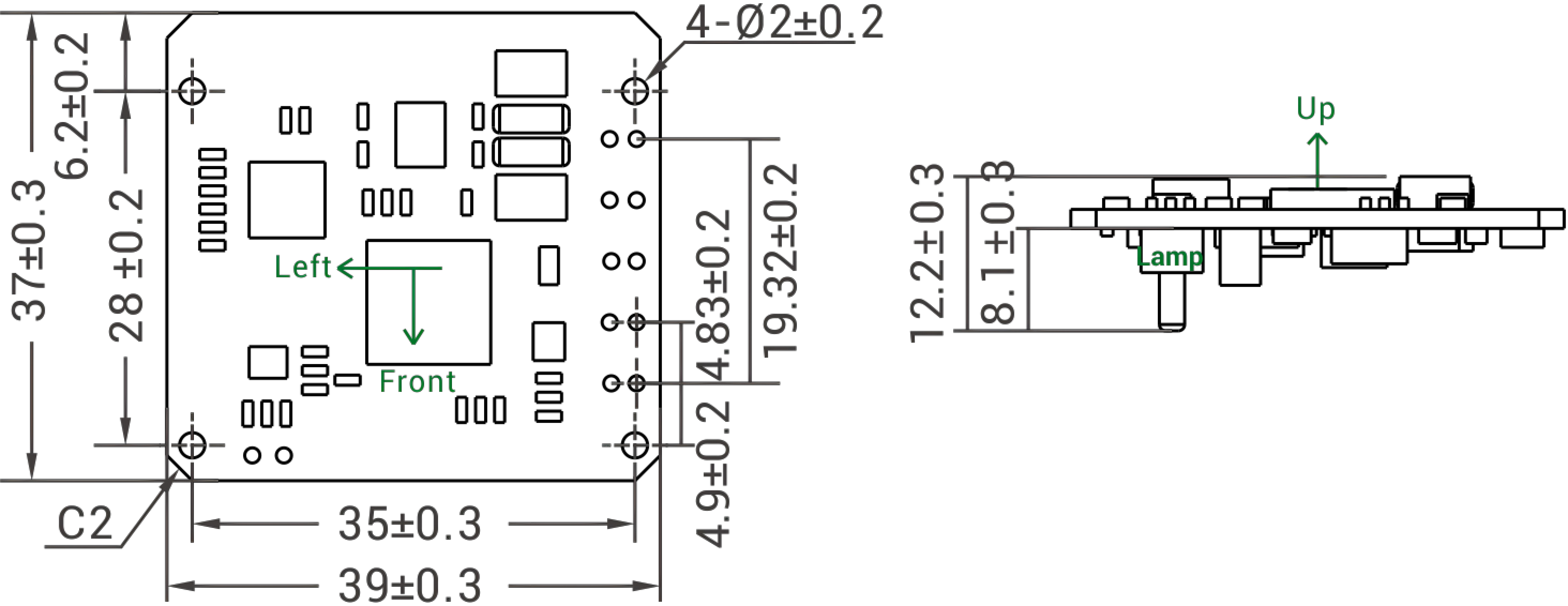
PCBA Dimension Diagram
Single panel dimensions: L39×W37×H12.2(mm)
Installation dimensions: L35×W28(mm)
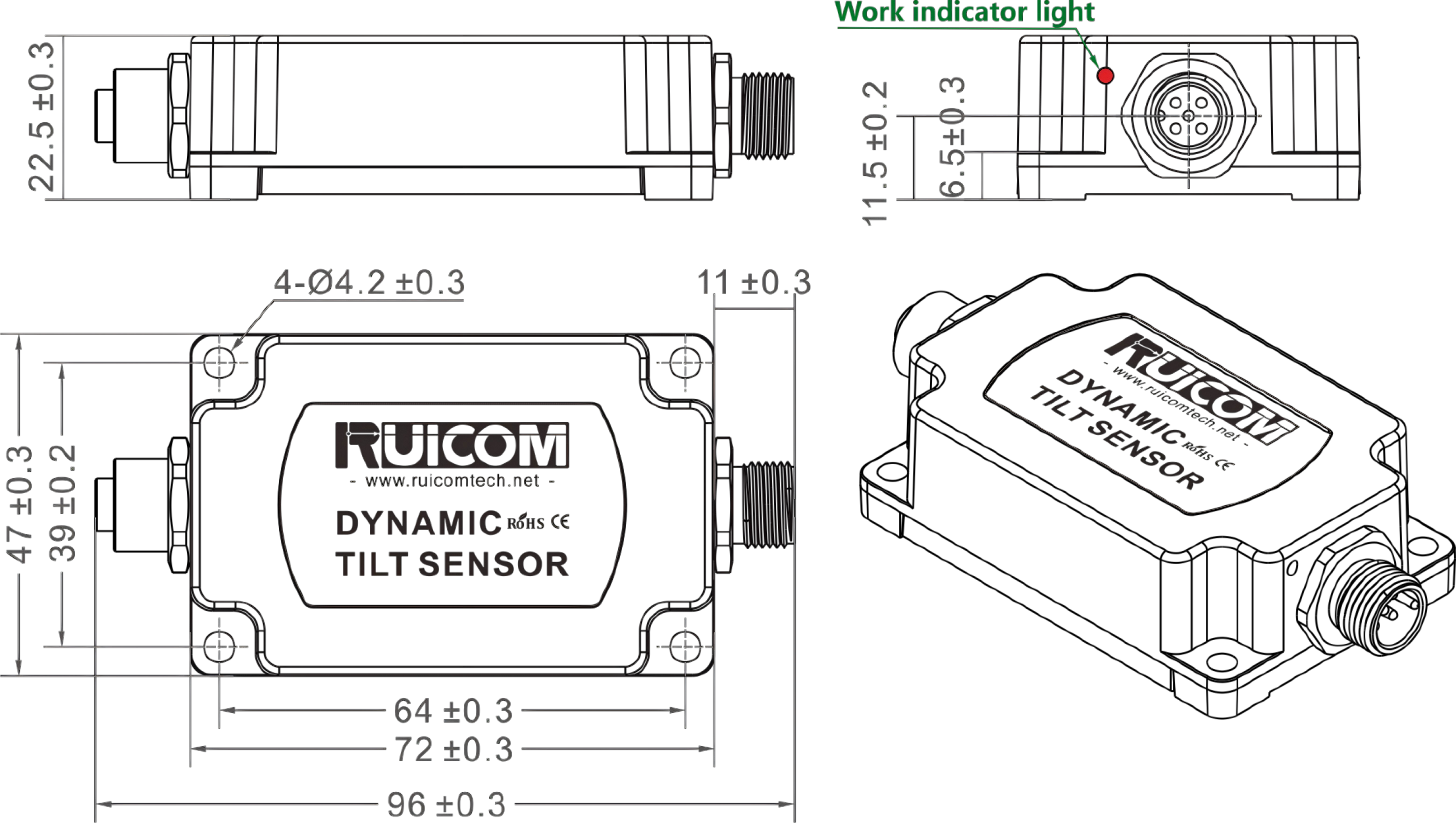
Single-head (male) connector housing dimension drawing
Shell Size: L83×W47×H22.5(mm)
Recommended screws: 4 M5 screws

head (male and female) connector housing dimension diagram
Shell Size: L96×W47×H22.5(mm)
Recommended screws: 4 M5 screws
Corrosion-resistant shell size diagram
Shell Size: L95.3×W56×H24.5(mm)
Recommended screws: 4 M5 screws


|
 STS Standard Output Tilt Sensor Inclinometer RS232 / TTL / RS485 Signal Output
LTS6 CAN2.0B Output Tilt Sensor Inclinometer For Aerial Work Platform
LTS6 Current Output Angle Tilt Sensor For Construction Hoisting Equipment
LTS6 Voltage Output Angle Tilt Sensor For Agricultural Machinery
LTS6 Digital Output Tilt Sensor Inclinometer For All Attitude Angle Measurement
GDS820 Industrial Digital Inclinometer High-Precision Dual Axis Tilt Sensor
DTS6-V1 Dynamic Tilt Sensor with Voltage Output
DTS6 Dynamic Inclinometer Tilt Sensor High Shock Resistant with Digital Output
DTS6 Dynamic Tilt Sensor High Shock Resistant with CANOpen Output
DTS6-A1 Dynamic Tilt Sensor with Current Output
STS Standard Output Tilt Sensor Inclinometer RS232 / TTL / RS485 Signal Output
LTS6 CAN2.0B Output Tilt Sensor Inclinometer For Aerial Work Platform
LTS6 Current Output Angle Tilt Sensor For Construction Hoisting Equipment
LTS6 Voltage Output Angle Tilt Sensor For Agricultural Machinery
LTS6 Digital Output Tilt Sensor Inclinometer For All Attitude Angle Measurement
GDS820 Industrial Digital Inclinometer High-Precision Dual Axis Tilt Sensor
DTS6-V1 Dynamic Tilt Sensor with Voltage Output
DTS6 Dynamic Inclinometer Tilt Sensor High Shock Resistant with Digital Output
DTS6 Dynamic Tilt Sensor High Shock Resistant with CANOpen Output
DTS6-A1 Dynamic Tilt Sensor with Current Output

