| Sign In | Join Free | My infospaceinc.com |
|
| Sign In | Join Free | My infospaceinc.com |
|
| Categories | Patient Monitor Parts |
|---|---|
| Model Number: | XM1 |
| Delivery Time: | 3-5 working days |
| Color: | White |
| Material: | Plastic |
| Operating Temperature: | -20°C to +70°C |
| Brand Name: | Edan |
| Connector Cutouts: | ECG, SpO₂, NIBP, temperature ports |
| Product Name: | Edan XM1 Outer Cover |
| Warranty: | 90 Days |
| Function: | Protective housing |
| Condition: | Good |
| MOQ: | 1 |
| Payment: | T/T, Western Union,Paypal |
| Payment Terms: | T/T, Western Union,Paypal |
| Company Info. |
| China World Technology Medical Equipment Service Group |
| Verified Supplier |
| View Contact Details |
| Product List |
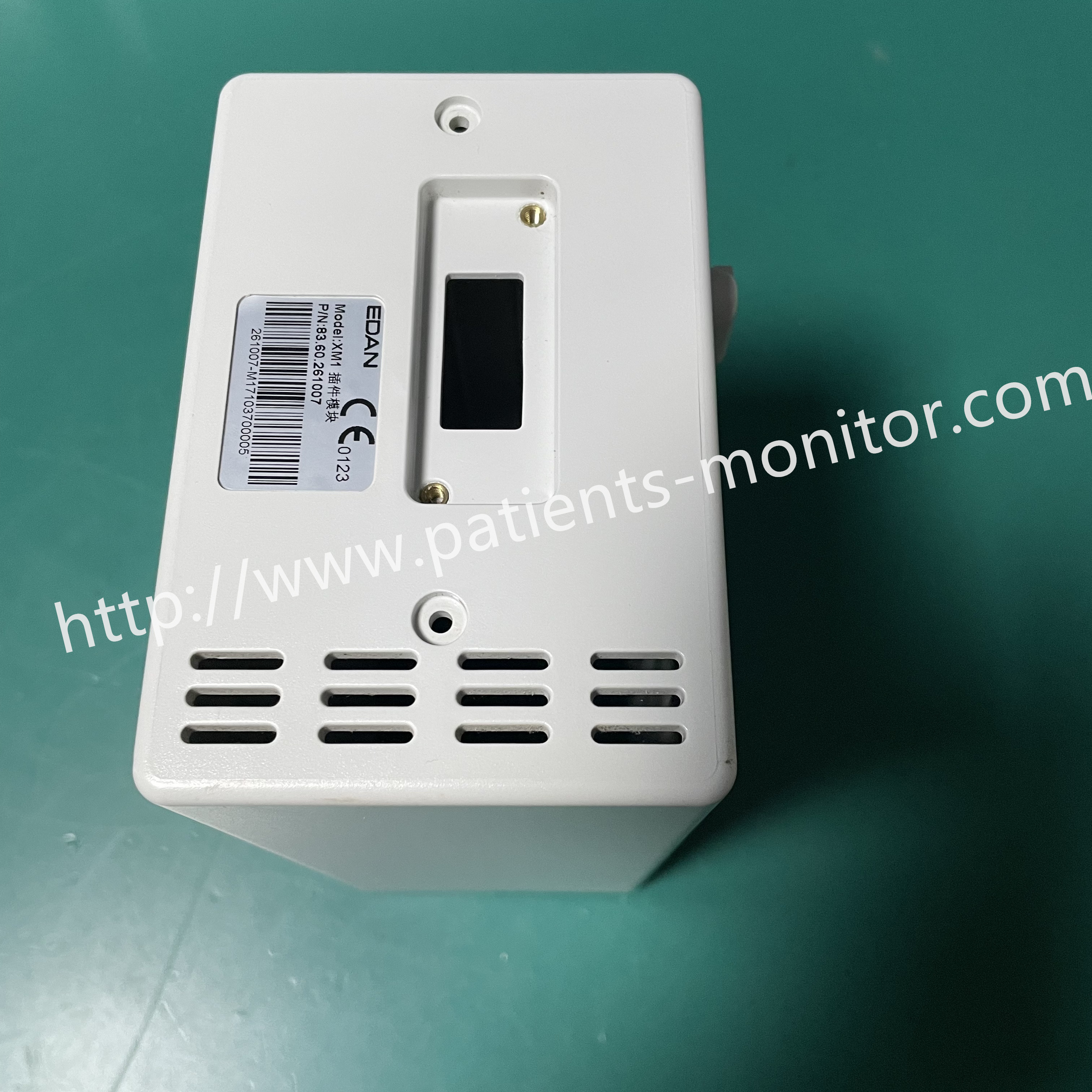
Edan XM1 Model Inner Frame Original Replacement Spare Part
Introduction
This outer casing shell is engineered as a direct replacement housing for the Edan XM1 module. It forms the external enclosure of the module unit, and all cutouts, mounting posts and internal rib structures are manufactured to match the original equipment design. The shell protects the internal electronic assemblies of the XM1 module, and it can be used to swap out cracked, scratched or damaged housings during equipment maintenance.

Functions
1. Protects the module's internal components. The cover shields the parameter board, NIBP pump and valves, SpO₂ board, and wiring from dust, fluid splashes, and physical impact during transport and daily use.
2. Positions the faceplate connectors precisely. The openings for ECG, SpO₂, NIBP, and temperature ports are molded to tight tolerances so that external cables and tubes mate correctly with the internal connectors every time.
3. Holds the keypad in alignment. The keypad board is mounted on the inner side of the module's operation panel, and the cover provides the positioning posts that keep the keypad aligned with the front membrane overlay.
Installation and Removal Method
1. Power supply to the Edan XM1 module must be fully disconnected before you start the work. Locate and remove the fixing screws on the original casing, then gently separate the old shell from the internal module assembly.
2. Align the internal positioning pillars and cutouts of the new
casing with the corresponding positions on the module. Secure the
new shell in place by reinstalling all original screws.
3.Double-check that the ventilation holes and display window are properly aligned once assembly finishes. Reverse these steps when disassembly is needed for future service.

|
 Patient Monitor Accessories Goldway UT4000 Monitor Blood Pressure Plate Great Value
Mindray PM7000 Patient Monitor Accessories Keyboard Silicone 7000-20-24395
Well-chosen Patient Monitor Mainboard Goldway G30 40 60 70 80 UT4000B UT6000 Monitor Motherboard
Patient Monitor Repair Parts GE Dash4000 Patient Monitor Flat Cable in ready
5 Leads Patient Monitor Parts Pm 7000 Portable Medical Monitor
V100 Monitor Controller Board , PWB Patient Monitor Accessories
25-250BPM Patient Monitor Parts 14V 3A Blood Pressure Monitor Plate
1024x768 MEC1000 Intellivue Patient Monitor Power Board For Clinic
VM8 Patient Monitor Parts Mainboard
Hospital Medical Equipment PHiliph MP20-MP70 Patient Monitor Repair Parts M3000-60003 Pump
Patient Monitor Accessories Goldway UT4000 Monitor Blood Pressure Plate Great Value
Mindray PM7000 Patient Monitor Accessories Keyboard Silicone 7000-20-24395
Well-chosen Patient Monitor Mainboard Goldway G30 40 60 70 80 UT4000B UT6000 Monitor Motherboard
Patient Monitor Repair Parts GE Dash4000 Patient Monitor Flat Cable in ready
5 Leads Patient Monitor Parts Pm 7000 Portable Medical Monitor
V100 Monitor Controller Board , PWB Patient Monitor Accessories
25-250BPM Patient Monitor Parts 14V 3A Blood Pressure Monitor Plate
1024x768 MEC1000 Intellivue Patient Monitor Power Board For Clinic
VM8 Patient Monitor Parts Mainboard
Hospital Medical Equipment PHiliph MP20-MP70 Patient Monitor Repair Parts M3000-60003 Pump

